- СВЕТИЛЬНИК АВАРИЙНОГО ОСВЕЩЕНИЯ
- Светильник teco dl 300a инструкция
- TECO S310+ Series Operation Manual
- Quick Links
- Troubleshooting
- Related Manuals for TECO S310+ Series
- Summary of Contents for TECO S310+ Series
- Page 3: Table Of Contents
- Page 4: Chapter 0 Preface
- Page 5: Chapter 1 Safety Precautions
- Page 6: During Power Up
- Page 7: During Maintenance
- Page 8: Chapter 2 Definition Of Model
- Page 9: Chapter 3 Ambient Environment And Installation
- Page 10: Environmental Precautions
- Page 11: Electrical Installation
- Page 12: Contactor And Circuit Breaker Specification And Wiring
- Page 13: Precautions For Peripheral Applications
- Page 16: Specifications
- Page 17: General Specifications
- Page 19: Wiring Diagram S310+ Series Inverter
- Page 20: Description Of Connection Terminals
- Page 21: Outline Dimension
- Page 23: Chapter 4 Software Index
- Page 25: Display Description
- Page 26: Function Of Digital Tube Display
- Page 27: Operational Examples Of Keypad
- Page 28: Control Mode Selection
- Page 29: S310+ Programmable Functions List
- Page 40: Parameter Function Description
- TECO E310 Series Operating Manual
- Quick Links
- Troubleshooting
- Related Manuals for TECO E310 Series
- Summary of Contents for TECO E310 Series
- Page 2: Table Of Contents
- Page 5: Chapter 0 Preface
- Page 6: Chapter 1 Safety Precautions
- Page 7: During Power Up
- Page 8: During Operation
- Page 9: Definition Of Model
- Page 10: Chapter 3 Ambient Environment And Installation
- Page 11: Environmental Precautions
- Page 12: Electrical Installation
- Page 13: Contactor And Circuit Breaker Specification And Wiring
- Page 14: Precautions For Peripheral Applications
- Page 15: Figure 3-4A) Installation Examples
- Page 16: Figure 3-5 Control Cable Requirements
- Page 17: Specifications
- Page 18: General Specifications
- Page 20: Wiring Diagram E310 Series Inverter
- Page 21: Description Of Connection Terminals
- Page 22: Outline Dimension
- Page 23: Figure 3-9 Frame Size 2 Dimensions
- Page 24: Chapter 4 Software Index
- Page 25: Operation Instruction Of The Led Keypad
- Page 26: Control Mode Selection
- Page 27: E310 Programmable Functions List
- Page 40: Parameter Function Description
- Page 41: Figure 4-4 Frequency Reference Limits
- Page 42: Figure 4-5 Terminal Board Drive Operation Modes
- Page 43: Figure 4-7 Drive Start/Stop Operation Sequences
- Page 45: Figure 4-8 Acceleration And Deceleration Prohibit
- Page 47: Figure 4-9 Up/Down Original Mode Example
СВЕТИЛЬНИК АВАРИЙНОГО ОСВЕЩЕНИЯ
СВЕТИЛЬНИК АВАРИЙНОГО ОСВЕЩЕНИЯ
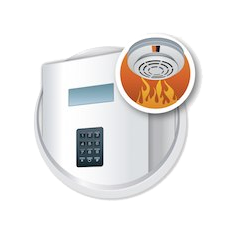
Светильники аварийного освещения данной серии ЛБА применяются для временного местного освещения рабочей зоны, освещения путей эвакуации, коридоров, запасных дверей или просто как переносные светильники.

Данные светильники используются в качестве аварийных, при отсутствии стационарного аварийного освещения в квартире или любом другом помещении. Питание такого аварийного освещения берётся от встроенного свинцового герметичного аккумулятора на 6 В.

Корпус светильника выполнен из пластика, материал рассеивателя света – полистирол. Светильники комплектуются линейными люминесцентными лампами диаметром 26 мм и мощностью 20 ватт. Минимальная продолжительность аварийного освещения – 240 мин. Оснащены ЭПРА. Номинальное напряжение 230 В. Цветовая температура света 6400К. Имеется возможность автоматического или ручного включение света. Ручное управление будет только если выдернуть вилку из розетки, или нажать на кнопку (без фиксации) «тест», и если светильник включен в сеть, – он не включается.


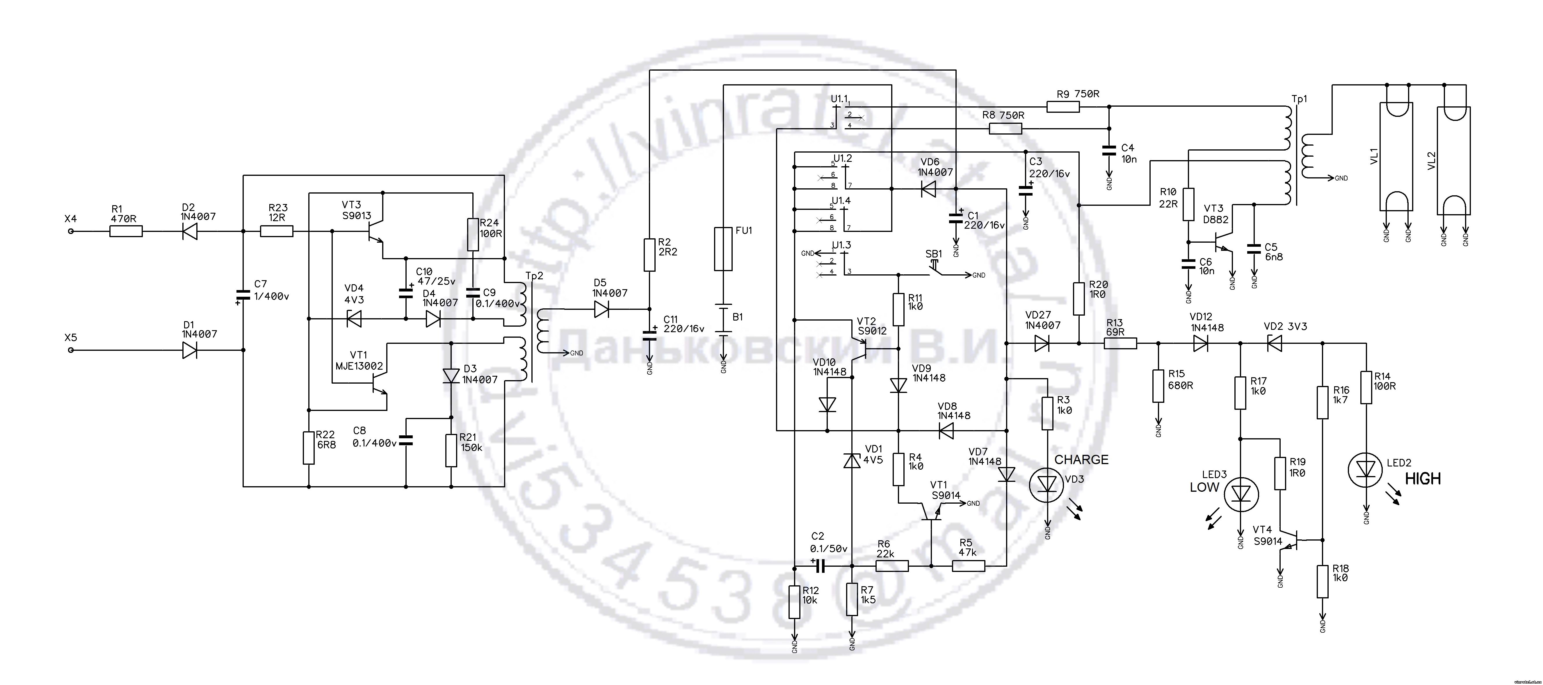
Схема представляет собой обычный двухтактный блокинг генератор на транзисторах D882. На транзисторе С9012 собран ключ, в его коллекторной цепи стоит стабилитрон, его задача не допустить полного разряда, пока не заряжен конденсатор С2, запускается ключ на Q1, шунтирует резистор R4 на массу и через диод VD9 открывается транзистор Q2, питание поступает на преобразователь. А на стабилитроне сделана обратная связь, чтоб удерживать первый транзистор отрытым. Теперь при снижении напряжения, до 5,9..6,0 напряжения не хватает пробить стабилитрон – схема обесточивается. Подробнее о преобразователях для люминесцентных ламп читайте здесь. S1 – это выключатель имеющий две функции: включить сам процесс зарядки, или включить лампу, когда нет напряжения. А на диодах VD7, VD8 и транзисторе Q1 сделан детектор пропадания напряжения сети, схема заработает если катод диода VD9 будет относительно массы, а его подпирает напряжение через открытый диод VD7. Заряд,как в большинстве дешёвых китайских устройств, идёт напрямую с выпрямителя через резистор 2 Ома.


На плате установлен предохранитель на 2 А. Имеется так-же возможность кроме сетевого, питания и от автоаккумулятора на 12 В. Адаптер сети 220/7.5 В выполнен по бестрансформаторной схеме, как в зарядках мобильных телефонов.

Материал предоставил: -igRoman-. Вопросы и комментарии на ФОРУМ
Светильник teco dl 300a инструкция
Приведенная схема светильника Ultralight System по схемотехнике похожа на подобные устройства других фирм.
Схема и краткое описание возможно пригодится при ремонте и эксплуатации.
Светильник аккумуляторный люминесцентный предназначен для обеспечения эвакуационного и резервного
освещения, а также как сетевой настольный светильник.
Потребляемая мощность в режиме зарядки — 10Вт.
Время работы от внутренней батареи при полном заряде, не менее 6ч. (с одной лампой и 4ч. с двумя лампами).
Время полного заряда батареи, не менее 14 ч.
Корпус изготовлен из полимерного пластика, рассеиватель из поликарбоната, аккумуляторная батарея кислотная 6В — 4,5Ач.
Проверить работу светильника, выявить в большинстве случаев неисправности возможно даже не вскрывая
корпус светильника, ориентируясь по яркости свечения светодиодов LOW и HIGH.
Для этого переключатель режима перевести с OFF в DC светодиод LOW или HIGH и лампы светильника должны
загораться. Когда лампы не засветились, переводим переключатель в режим AC подключаем в сети, если после
этого светильник не работает нужно смотреть плату управление и лампы.
Если светильник нормально работает от сети, переводим, переключатель в режим DC, нажать кнопку TEST,
светильник должен засветится. Даже 1,5-2В лампы тускло загораются, при нажатии кнопки TEST. Отсюда вывод
напряжения на аккумуляторе меньше 5В. Светодиод LOW ярко светит при напряжении на батареи 5.9В,
при уменьшении напряжения яркость будет падать и при 2В отключается, это показывает разряд аккумулятора .
Свечение индикатора HIGH свидетельствует напряжение на аккумуляторе 6.1В и выше. При напряжении 6.4В
светодиод должен ярко светить, с уменьшением напряжение падает яркость светодиода, при 6.0В индикатор
Когда на аккумуляторе 6.0В, погаснут оба индикатора LOW и HIGH.
Частые дефекты светильника.
Не работает зарядка аккумулятора.
Проверить сетевой шнур. Не исправный блок питание. Часто проблемой отказа нормальной работы блока
питания является очень плохой монтаж. Нужно проверить все пайки подозрительные пропаять. Проверить
транзисторы блока питания, если не исправный один с них нужно менять сразу и другой.
Практика показывает, что виновником повторного ремонта будет ранее не замененный транзистор.
В режиме AC работает, DC не работает.
Светодиоды LOW /HIGH не светят, перегорел предохранитель.
В большинстве случаем обрыв соединяющих проводников платы, или выхода из строя аккумулятора
TECO S310+ Series Operation Manual
Quick Links
Troubleshooting

Related Manuals for TECO S310+ Series
Summary of Contents for TECO S310+ Series
- Page 1 Microprocessor Controlled I G B T Drive Inverter Motor Speed Regulator Operation Manual S310+ Series 400V class 0.75
6.7kVA)
Page 2 Distributor: Add: Wuxi High&New Technology Industry Development Zone. Block 65-C ,WuXi, Jiangsu ,China. Postcode:214028 Tel: +86-0510-85227555 Fax: +86-0510-85227556(Electronic) 2018. 4 Website: www.taian-technology.com This manual may be modified when necessary because of improvement of the product, modification, or changes in specification, this manual is subject to change without notice.
Page 3: Table Of Contents
Page 4: Chapter 0 Preface
Page 5: Chapter 1 Safety Precautions
Page 6: During Power Up
Page 7: During Maintenance
Page 8: Chapter 2 Definition Of Model
Page 9: Chapter 3 Ambient Environment And Installation
+50℃(Power distribution panel: -10℃
Page 10: Environmental Precautions
Page 11: Electrical Installation
Page 12: Contactor And Circuit Breaker Specification And Wiring
Page 13: Precautions For Peripheral Applications
Page 16: Specifications
480V model 4 0 5 S3 1 0 +-□□□-X XX 4 0 1 4 0 2 4 0 3 Horsepower(HP) Max Applicable Motor Output 0. 75 1. 5 2. 2 3. 7 (KW) Rated Output Current(A) 2.
Page 17: General Specifications
400.00 Hz 140% /1Hz (SLV mode) Starting torque 1:50 (SLV mode) Speed control range ±1% (SLV mode) Speed control accuracy Setting resolution Digital: 0.01Hz, Analog: 0.06Hz/ 60Hz(10bits) Keypad setting Set directly with▲▼.
Page 18 FUSE protection The motor stops after FUSE melt 400V class: DC Voltage>820V Over Voltage 400V class: DC Voltage>380V Under Voltage Momentary Power Restart can be initiated with spin start . Loss Restart Stall protection can be set in acceleration ,deceleration ,constant Stall protection speed.
Page 19: Wiring Diagram S310+ Series Inverter
Page 20: Description Of Connection Terminals
5HP. rapidly. (refer to specifications of the braking resistor) Inverter outputs Descriptions of control circuit terminals.
Page 21: Outline Dimension
Page 23: Chapter 4 Software Index
Page 25: Display Description
Page 26: Function Of Digital Tube Display
Page 27: Operational Examples Of Keypad
Page 28: Control Mode Selection
Page 29: S310+ Programmable Functions List
9.99 1.00 Pulse frequency multiple Pulse input filtering 01-16 0
100 coefficient Count value reaches the 01-17 0
9999 setting value Pulse input counting filtering 01-18 1
100 coefficient.
Page 33 Group Multi-Speed Parameters Code Parameter Name Setting Range Default Unit Attribute 0: Part acceleration and deceleration time are set by acceleration and Acceleration and Deceleration 03-00 deceleration time1 Selection of Multi-Speed 1: Part acceleration and deceleration time are set by independently Frequency Setting of 03-01 0.00
400.00.
Page 34 Group Multi-Speed Parameters Code Parameter Name Setting Range Default Unit Attribute Acceleration Time Setting of 03-31 0.1
3600.0 10.0 Multi Speed 7 Deceleration Time Setting of 03-32 0.1
3600.0 10.0 Multi Speed 7 03-33
03-48 Reserved Group Start/stop command group Code Parameter Name Setting Range.
Page 35 Group V/F command group Code Parameter Name Setting Range Default Unit Attribute 05-10 0.10
400.00 1.50 Minimum Frequency 05-11 Minimum Frequency Voltage 400V:0.0
528.0 22.8 05-12 Reserved Low-pass Slip compensation 05-13 0.05
10.00 0.10 Filter time 05-14 Reserved Auto-Torque compensation 05-15 *1*5 0.1
1000.0.
Page 36 Group Protection Parameters Code Parameter Name Setting Range Default Unit Attribute Stall Prevention Level In Run 07-03 50
200 Mode (%) over voltage Prevention Level in 80
100 (OV %) 07-04 Run Mode (%) 0: Enable motor Protect by relay 07-05 Electronic Motor Overload Protection Operation Mode OL1.
Page 40: Parameter Function Description
3600.0】.
Page 42 ※Note: 1.As 3 wire control mode is selected, the terminal S1, S2 and S3 is not controlled by 01-00, 01-01 and 01-02. 2. 10-01=1, the reverse command is unavailable. 00-12 Jog Frequency 【1.00
25.00】Hz range 00-13 Jog Acceleration Time 【0.1
25.5】Sec range 00-14 Jog Deceleration Time 【0.1
25.5】Sec.
TECO E310 Series Operating Manual
Quick Links
Troubleshooting
Related Manuals for TECO E310 Series
Summary of Contents for TECO E310 Series
- Page 1 Microprocessor Controlled I G B T Drive Inverter Motor Speed Regulator Operating Manual E310 Series 200V class 0.4
Page 2: Table Of Contents
Page 5: Chapter 0 Preface
Page 6: Chapter 1 Safety Precautions
Page 7: During Power Up
Page 8: During Operation
Page 9: Definition Of Model
240V 50/60Hz → Output specifications O/P: AC 3PH 0
240V 1.7 KVA 4.5 A TECO Electric & Machinery co., Ltd. E310Series: 0 — 2 01 — H Supply voltage Specification 200Vclass 400Vclass Adhibition.
Page 10: Chapter 3 Ambient Environment And Installation
Page 11: Environmental Precautions
Page 12: Electrical Installation
Page 13: Contactor And Circuit Breaker Specification And Wiring
Page 14: Precautions For Peripheral Applications
Page 15: Figure 3-4A) Installation Examples
Page 16: Figure 3-5 Control Cable Requirements
Page 17: Specifications
Page 18: General Specifications
400.00 Hz Range 150%/1Hz ( Vector) Start control torque 1:100 ( Vector) Speed control range ±0.5% (Vector) Speed Control Precision Digital: 0.01Hz, Analog: 0.06Hz/ 60Hz(10bits) Setting resolution Set directly with▲▼ keys or the VR on the keypad Keypad setting Five digital LED and status indicator;.
Page 19 Item E310 1. Control by RS485 2. One to one or one to many control. Communication Control 3. BAUD RATE/STOP BIT/PARITY/bit can be set About 20﹪, the model below 20HP with built-in braking Braking Torque transistor and the specified external braking resistors can provide 100% 14-120℉(-10
Page 20: Wiring Diagram E310 Series Inverter
Page 21: Description Of Connection Terminals
2HP, when it is required to stop a high inertia load rapidly. (refer 380V:1
5HP to specifications of the braking resistor) Inverter outputs.
Page 22: Outline Dimension
Page 23: Figure 3-9 Frame Size 2 Dimensions
Page 24: Chapter 4 Software Index
Page 25: Operation Instruction Of The Led Keypad
Page 26: Control Mode Selection
06-05 will be limited by one size higher or lower than TECO standard motor specification. In VF MODE control, there is no limitation.
Page 27: E310 Programmable Functions List
400.00 50.00/60.00 00-08 Frequency Lower Limit (Hz) 0.01
399.99 0.00 00-09.
20mA AVI/ACI analog Input signal type 02-00 0
20mA 02-01 AVI Signal Verification Scan 1
100(x 4ms) 02-02 AVI Gain (%) 0
1000.
Page 31 3-preset Frequency function group Function Factory Description Range/Code Remarks Code No. Setting 0 : common (Is uniform time( Acc1/Dec1or Acc2/Dec2) Preset Speed Control mode 03-00 Selection 1 : special (is single time Acc0/Dec0
Acc7/Dec7) 03-01 Preset Speed 0 (Hz) 0.00
400.00 5.00 Keypad Freq 03-02.
30.0 10.0 (Torque Boost) (%) 05-01 Motor No Load Current(Amps AC) —— 05-02 Motor rated Slip Compensation (%) 0.0
264.0 05-03 v/f max voltage 440V series : 323.0
528.0.
300 07-12 Over torque Activation Delay Time (S) 0.0
25.0.
3600.0 10.0 10-06.
Page 38 12-User parameter group Function Factory Range/Code Description Remarks Code No. Setting 12-00 Drive Horsepower Code —— 12-01 Software Version —— —— 12-02 Fault Log (Last 3 Faults) —— Accumulated Operation Time1 12-03 0
23 —— (Hours) Accumulated Operation Time2 12-04 0
65535 —— Days) 0 : Time Under Power.
Page 39 Function Factory Description Range/Code Remarks Code No. Setting Auto _ Run Mode 13-07 Frequency Command 7 13-08
Reserved Reserved 13-15 Auto_ Run Mode Running 13-16 Time Setting 0 Auto_ Run Mode Running 13-17 Time Setting 1 Auto_ Run Mode Running 13-18 Time Setting 2 Auto_ Run Mode Running.
Page 40: Parameter Function Description
Page 41: Figure 4-4 Frequency Reference Limits
Page 42: Figure 4-5 Terminal Board Drive Operation Modes
Page 43: Figure 4-7 Drive Start/Stop Operation Sequences
400.00 00-13 : Jog Acceleration Time (MFIT) (S) =0.1
25.5 00-14 : Jog Deceleration Time (MFIT) (S) =0.1
25.5 Example:When 1-00(S1)=5,1-01(S2)=6 (Jog), Jog run is controlled by external terminals, S1 on is.
Page 44 12 : Up Command 13 : Down Command 14 : Main/sub Control Signal Select 15 : PID Function Disabled 16 : Integration Value Resets to Zero 17 : Reset 18 : KEB function 19 : Auto _ Run Mode 20 : Counter Trigger Signal 21 : Counter Reset A.
Page 45: Figure 4-8 Acceleration And Deceleration Prohibit
05=14 Main/sub Frequency Command Selection When External multifunction input terminals are off, the inverter Frequency Command is operated by 00-05. When External multifunction input terminals are on, the inverter Frequency Command is operated by 00-06. 12. 01-00
05=15(PID Function Disable) When the PID Function Disable is ON, PID is not controlled by 09-00.
Page 47: Figure 4-9 Up/Down Original Mode Example
5.00 There are two modes covered below: 1 .01-07 = 0.00, the operation is just as the original one. When the UP terminal is ON, the frequency increases while the DOWN terminal is ON, the frequency decreases. (Refer to the following graph).